

Location (Explanation) Fuse Box Diagram Renault Clio 2, Symbol, Dacia Logan (1998-2005)
Location (Explanation) Fuse Box Diagram Renault Clio 2, Symbol, Dacia Logan (1998-2005).
HERE you can find the Fuse Box Set for Renault Clio 2, Symbol, Dacia Logan (1998-2005): — https://amzn.to/4lNDdph
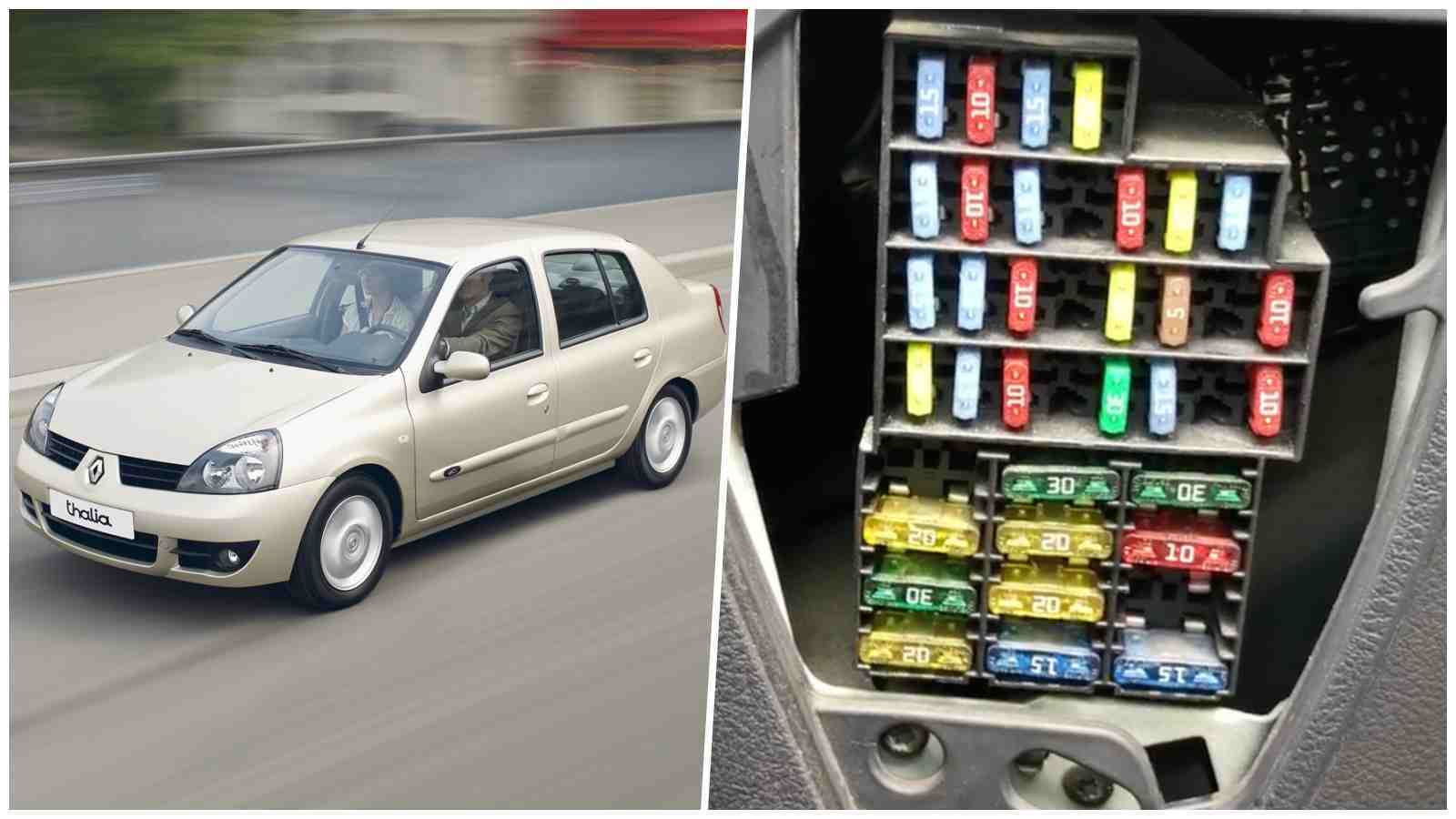
Quickly find out the locations and explanation of the fuses in the electrical panel of Renault Clio 2, Symbol and Dacia Logan (1998–2005). Practical guide for identifying, values and safe replacement of fuses.
HERE you can find Renault, Dacia Accessories AT THE BEST PRICE: https://s.click.aliexpress.com/e/_c3AZURjr
Renault Clio 2 (1998–2005) has two main fuse panels: one in the passenger compartment and one in the engine compartment. Knowing the location and function of each fuse helps you quickly detect electrical problems (lights, central locking, air conditioning, glow plugs, radio, etc.) and avoid costly breakdowns.
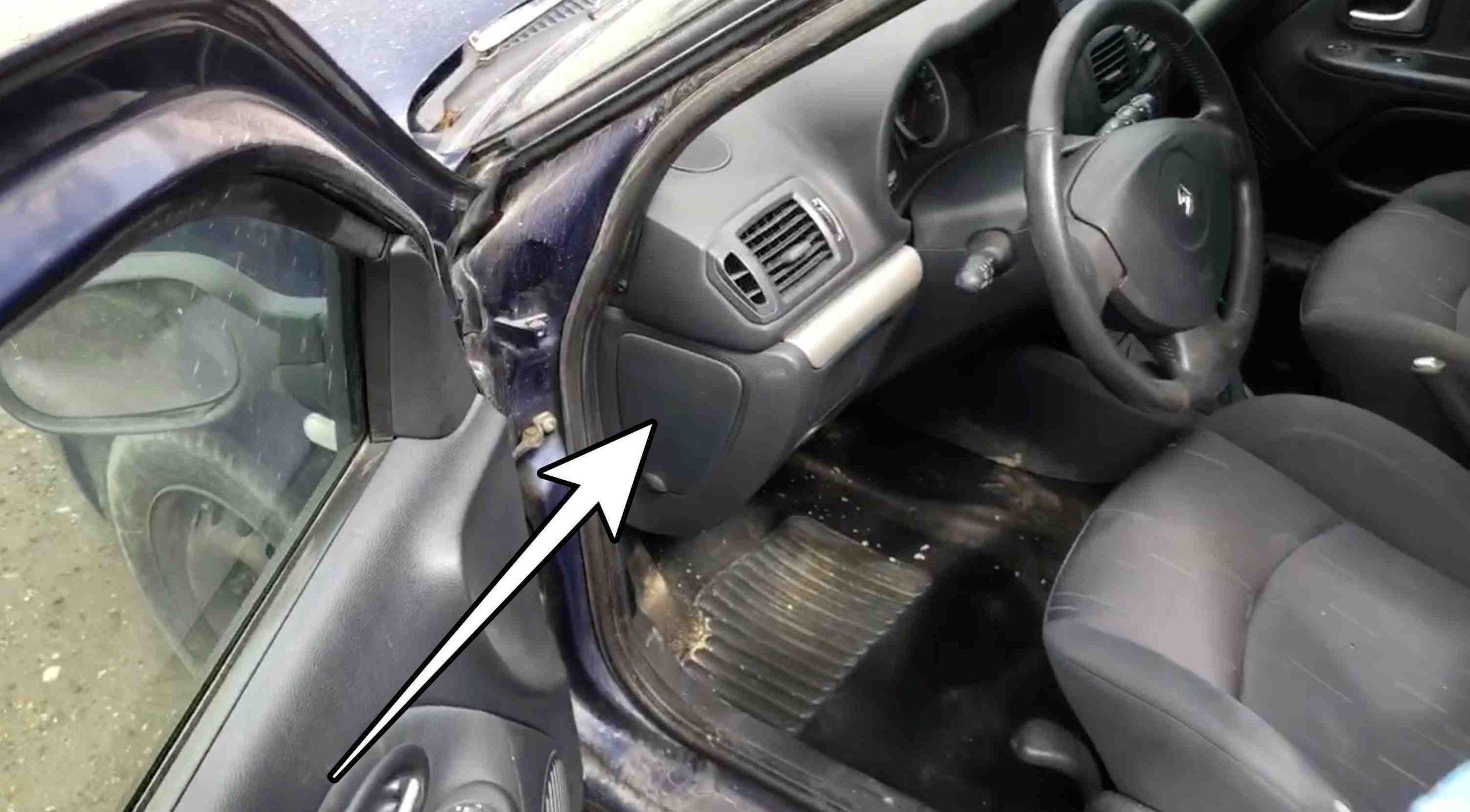
Passenger compartment fuse panel: located on the left of the dashboard, behind a plastic cover.
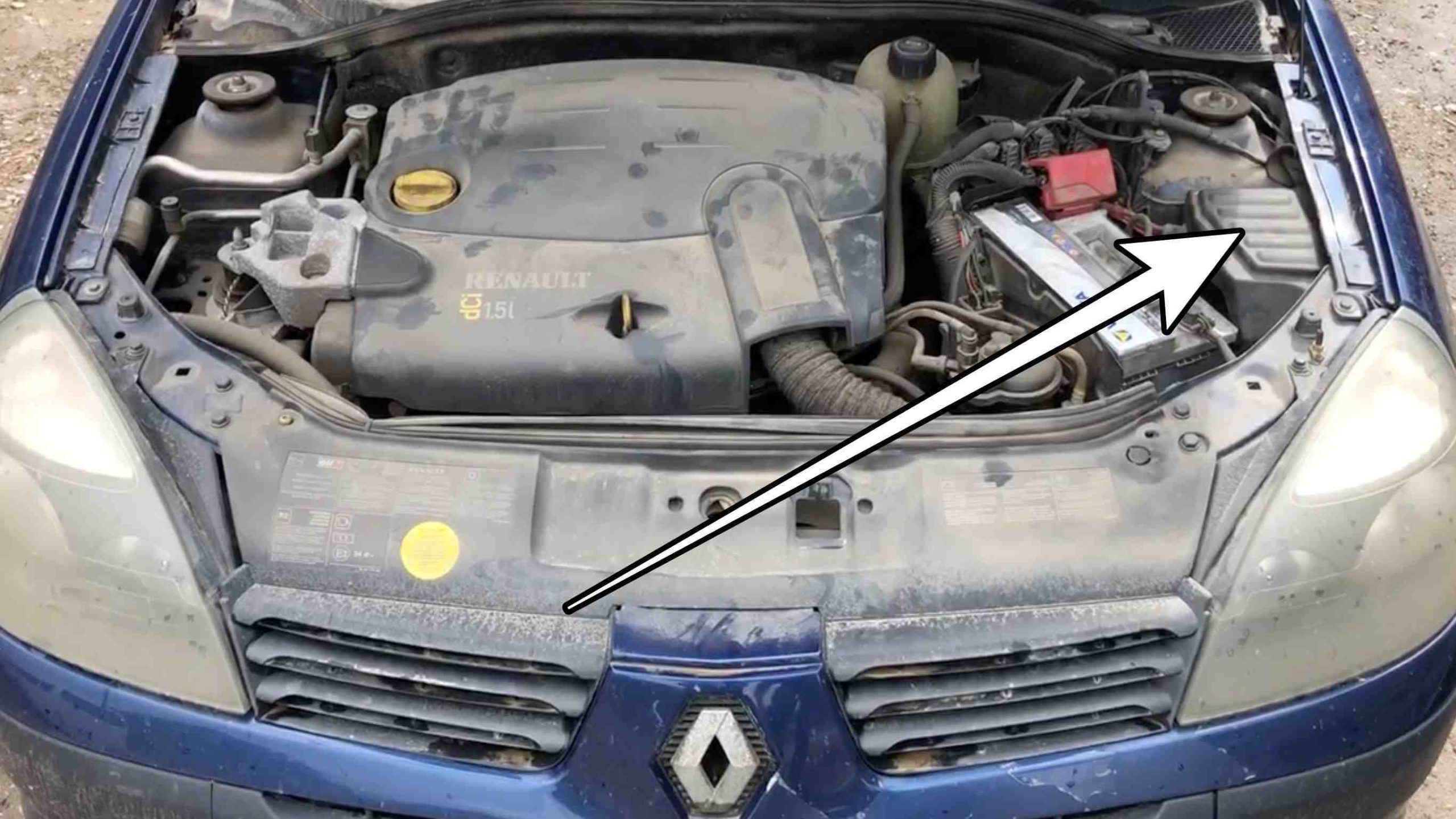
Engine compartment fuse panel: located on the left side of the engine compartment, near the battery or the left wing.
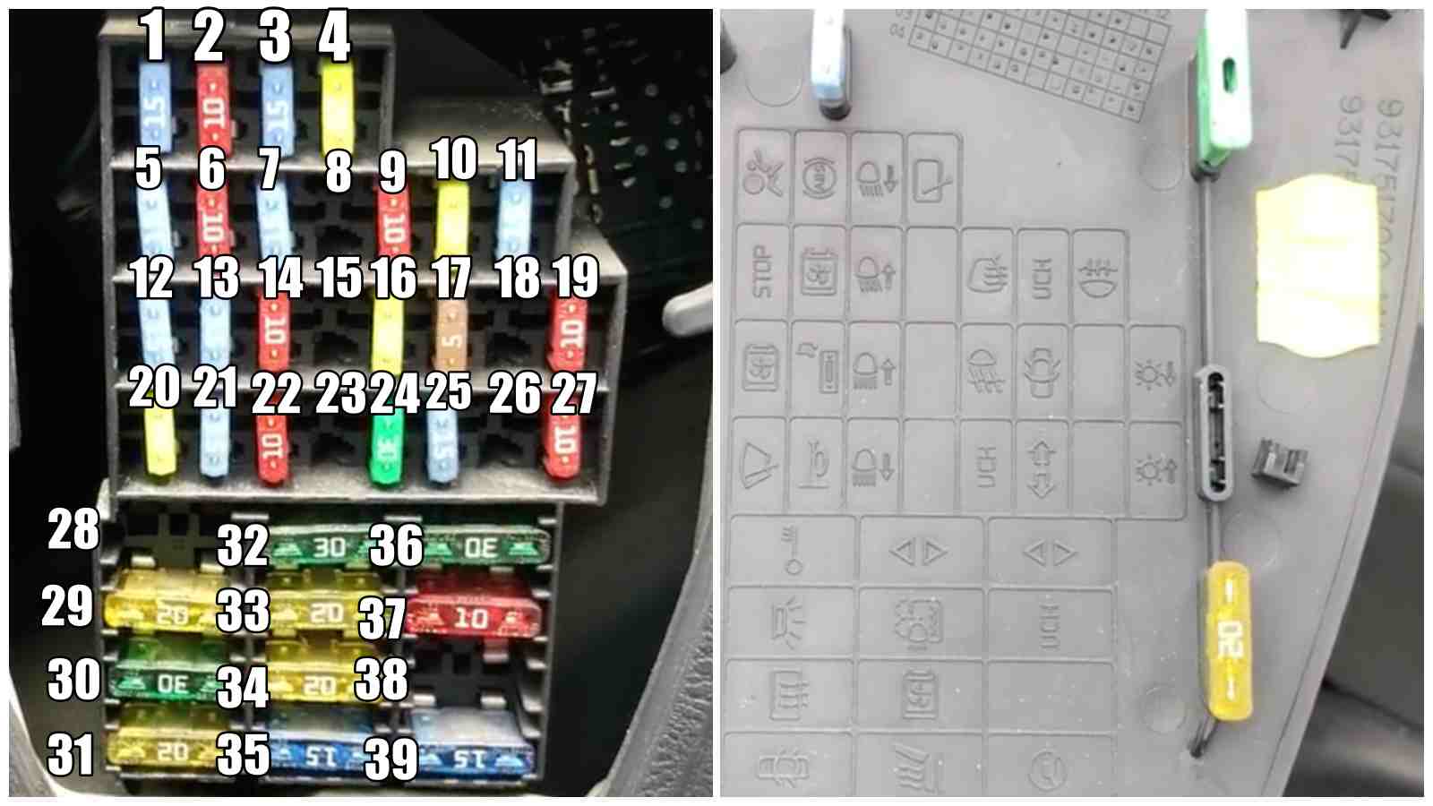
Fuse diagram and meaning (common examples).
Note: numbering may vary depending on engine and equipment — also consult your car manual.
Below you can find Fuse Box Diagram for the interior electrical panel:
|
Pozitie siguranta |
Amperaj
(A) |
Semnificatie |
|---|---|---|
|
1 |
15 A |
Airbag |
|
2 |
10 A |
ABS System |
|
3 |
15 A |
Left hand dipped headlight |
|
4 |
20 A |
Rear screen wiper via UCH |
|
5 |
15 A | Brake lights, Instrument panel, Shift pattern control, Diagnostic socket, Driving school, Opening warning light, Cruise control speed limiter control, Mobile phone connection, Electric door mirror control |
|
6 |
10 A | Multi-timer unit, Air conditioning computer |
|
7 |
15 A | Right hand dipped headlight |
|
8 |
– | – |
|
9 |
10 A | Heated door mirrors |
| 10 | 20 A | Driver’s electric windows via UCH |
|
11 |
15 A | Rear fog light |
|
12 |
15 A | Windscreen wiper combined control, Reversing light switch, Air conditioning control panel, Passenger compartment temperature sensor fan, Air conditioning control unit, Footwell vents air conditioning distribution motor, Rain sensor computer, Starter relay, Discharge bulb ECU, Headlight adjuster motors |
|
13 |
15 A | Radio, Cigarette lighter, Clock, Courtesy mirror, Heated rear screen relay, Central communication unit |
|
14 |
10 A | Right head main beam headlight |
|
15 |
– | – |
|
16 |
20 A | Front fog lights |
|
17 |
5 A | Multi-timer unit / Diagnostic socket / Door locking central control / Instrument panel / Decodor unit |
|
18 |
– | |
|
19 |
10 A | Left hand side lights – interior control lighting |
|
20 |
20 A | Windscreen wiper |
|
21 |
15 A | Horn |
|
22 |
10 A | Left hand main beam headlight |
|
23 |
– | |
|
24 |
30 A | Passenger electric windows |
|
25 |
15 A | Indicators and hazard warning lights |
|
26 |
– | – |
|
27 |
10 A | Right hand side lights – interior control lighting |
|
28 |
– | – |
|
29 |
20 A | Consumer cut-out / Interior lights / Radio / Clock |
|
30 |
30 A | Heated rear screen via UCH |
|
31 |
20 A | Central door locking via UCH |
|
32 |
30 A | Reserved |
|
33 |
20 A | Headlight washers |
|
34 |
20 A | Heating & Air Conditioning Fan unit |
|
35 |
15 A | Heated seats via UCH |
|
36 |
30 A | Passenger electric windows via UCH |
|
37 |
10 A | assenger compartment ECU |
|
38 |
– | – |
|
39 |
15 A | Electric power steering |
Below you can find Fuse Box Diagram for the engine compartment electrical panel:
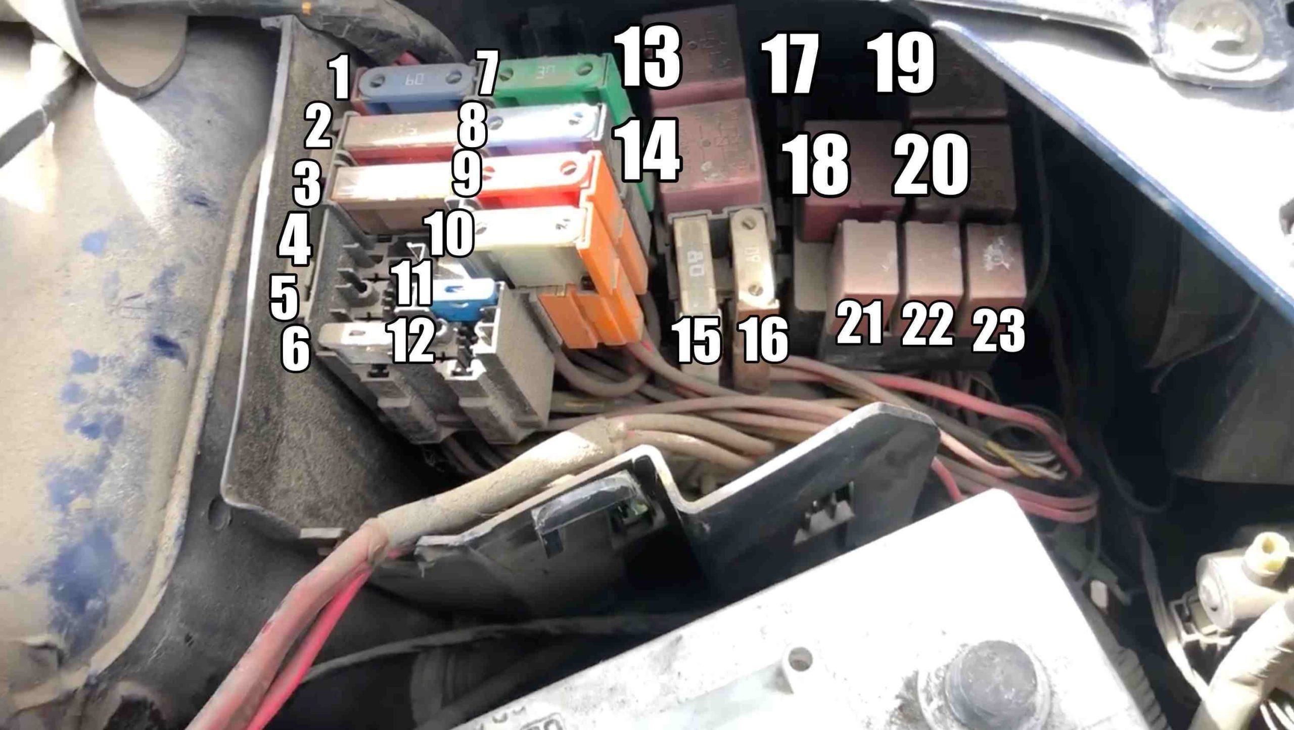
|
Pozitie siguranta |
Amperaj
(A) |
Semnificatie |
|---|---|---|
|
1 |
60 A | Dashboard |
|
2 |
50 A | Engine functions with air conditioning |
|
3 |
– | – |
|
4 |
5 A | Injection |
|
5 |
30 A | Engine functions with heater |
|
6 |
30 A | Injection |
|
7 |
30 A | Air conditioning fan |
|
8 |
60 A | Dashboard |
|
9 |
50 A /
60 A |
Anti-lock Braking System (50A) or Electronic Stability Program (60A) |
| 10 | 25 A | Anti-lock Braking System, for ABS 8.0 (solenoid valves) |
|
11 |
15 A | Injection-ignition |
|
12 |
5 A | Automatic gearbox |
|
13 |
||
|
14 |
||
|
15 |
||
|
16 |
||
|
17 |
R | Transmission shift fluid primary pump relay (D4F, sequential manual transmission) |
|
18 |
R | Engine coolant blower motor relay(with AC) |
|
19 |
R | AC compressor clutch relay |
|
20 |
R | Fuel pump (FP) relay |
|
21 |
R | Anti-percolation engine coolant blower relay/engine coolant blower motor relay-low speed |
|
22 |
R | Starter motor relay |
|
23 |
R | Engine control (EC) relay |
Replace the fuse with one of the same value (amperage) — do not use a fuse with a higher amperage.
If a fuse blows immediately after replacement, there is a short circuit; check the circuits before replacing again.
Keep a set of spare fuses and a fuse puller or clip in the car.
Consult your model-specific manual or an authorized service center for the exact diagram and detailed diagrams.